
Precision Surface Finishing Solutions improve consistency in high-tolerance parts by controlling the last variables that machining alone often leaves behind: peak height, waviness, edge condition, embedded debris, local heat effects, and the way a surface actually contacts a mating component. In electrical equipment and related assemblies, those details influence contact resistance, sealing behavior, dielectric spacing, optical alignment, fatigue initiation, and the repeatability of downstream bonding or coating steps. When tolerances are narrow, the finishing stage is not a cosmetic operation. It is where a part either converges toward specification or drifts into unstable performance from lot to lot.
The practical problem is that many parts can meet dimensional requirements on a drawing while still behaving inconsistently in service. A stamped copper contact may show acceptable thickness and outline but carry burr remnants that disturb mating force. A ceramic guide surface may pass a nominal flatness target but retain isolated high spots that tilt a ferrule under load. A stainless shaft may look smooth under low magnification while preserving directional scratches that interfere with seal life. Precision Surface Finishing Solutions are used to narrow those hidden variations by making the final surface state more predictable, not just the nominal shape.
In high-tolerance work, consistency starts with understanding which surface attributes matter for the actual function of the part. Roughness average alone rarely explains process stability. Surface lay, material pullout, edge roll, subsurface damage, and contamination film can matter more than a single arithmetic roughness value. This is particularly relevant in electrical equipment and supplies, where a finished part may need to carry current, maintain optical alignment, resist corrosion, or accept an adhesive with controlled wetting. A finishing process that gives a low Ra but leaves fractured grains at the surface can still create erratic performance if those defects break free during assembly or field vibration.
Where Variation Usually Enters the Finishing Stage
Most inconsistency is introduced through small changes that are easy to overlook because they sit outside the part drawing. Abrasive particle size distribution, backing film stiffness, platen flatness, fixture compliance, slurry concentration, contact pressure, and dwell time all shape the final result. Even storage conditions can matter. If lapping film absorbs moisture unevenly, or if polishing pads harden over time, two shifts running the same nominal recipe may produce different edge radii and different material removal rates.
Material response adds another layer. Aluminum, copper alloys, hardened steel, engineering ceramics, glass, silicon, ferrite, and polymer composites do not transition through abrasive stages the same way. Ductile materials may smear before they cut cleanly. Brittle materials may micro-chip if the abrasive step-down is too aggressive. Fiber-optic ferrule materials can exhibit subtle geometry drift if pressure distribution is not centered. A finishing method that is stable on one substrate may generate broad variation on another, even when the machine settings look reasonable.
Common misjudgments often come from treating the finishing process as a universal sequence: coarse, medium, fine, final polish. That structure is useful, but it is not enough. The real issue is whether each stage removes the damage pattern from the previous stage without introducing a new one that is harder to control. If a coarse abrasive leaves deep directional grooves and the intermediate stage does not fully reset that topography, the final polish may only soften the appearance of the marks while preserving enough geometry distortion to affect fit or signal performance.
Consistency Depends on Surface Function, Not Surface Shine
High-tolerance parts in electrical equipment often operate through interfaces. Contacts touch contacts. Ferrules align fibers. Bushings guide shafts. Heat sinks meet thermal interface materials. A polished appearance may have no direct relationship to the interface behavior needed in service. In some applications, a slightly textured but uniform surface performs better than a mirror finish because it stabilizes lubricant retention or adhesive spread. In others, such as optical end-face work or ceramic sealing faces, a very fine finish is necessary because even small defects act as optical scatter points or leakage paths.
This is why Precision Surface Finishing Solutions are usually evaluated against functional outcomes linked to the interface. For conductive components, stable asperity distribution can help produce more repeatable real contact area under fixed force. For insulating ceramics, controlled edge finish may reduce crack initiation during insertion or torque loading. For optical components, reduced scratch depth and better geometry control lower the risk of misalignment and signal loss. The process objective is therefore tied to a measurable use condition, not to visual smoothness alone.
Surface consistency also influences assembly behavior. A connector component with a narrow tolerance stack can still assemble unpredictably if one mating surface has variable friction caused by inconsistent polishing residue or abrasive embedment. Operators may compensate by adjusting force or reworking parts, which can mask the underlying instability for a while. Over time, that drives sorting, re-inspection, and unexplained variation in field returns. A stable finishing process reduces the need for those compensations because the interface behaves the same way more often.
Reading the Surface as a Process Record
A finished surface preserves clues about the process that created it. Under suitable magnification, a surface can reveal whether removal was primarily cutting, plowing, smearing, brittle fracture, or chemical-mechanical action. For high-tolerance parts, those clues matter because they indicate whether the finishing sequence is robust or operating close to failure. Random isolated pits may suggest contamination or particle agglomeration. Directional scratches that survive the final stage often indicate incomplete removal of the prior abrasive damage. Edge haze around a polished zone can point to pressure concentration or fixture tilt.
In metal components, the distinction between smeared material and cleanly cut material is especially important. Smearing can reduce apparent roughness while trapping residual stress or creating unstable oxide behavior. For copper and copper alloys used in contacts and conductive elements, a surface that looks bright may still show dragged material over grain boundaries. Under loading or thermal cycling, that surface can change more rapidly than a properly refined one. Finishing consistency therefore has to be verified by both metrology and microstructural observation where needed, especially during process development.
For brittle materials such as ceramics, ferrite, glass, or silicon-based substrates, the concern shifts toward subsurface damage. A final polish can hide shallow fracture networks that later affect strength, optical behavior, or coating adhesion. If the process sequence removes less material than the damage depth generated by an earlier stage, the part may carry invisible defects into service. In those cases, consistency requires disciplined control over the entire removal budget, not just the final pass.
Abrasive Selection Has Direct Consequences for Tolerance Stability
The abrasive itself influences consistency long before machine parameters come into play. Diamond, aluminum oxide, silicon carbide, cerium oxide, and silicon dioxide each remove material through different mechanisms and suit different substrates. Diamond is often chosen where hardness and removal control are central, but grade consistency, particle shape, and concentration affect whether it cuts cleanly or leaves random deep tracks. Aluminum oxide can be effective for many metals and some ceramics, yet friability and backing support determine whether it keeps generating fresh cutting edges or shifts into rubbing. Silicon carbide cuts aggressively on many hard materials but may be too severe for a delicate transition step. Cerium oxide is associated with glass and some optical polishing conditions where chemical interaction contributes to the finish. Silicon dioxide can support ultra-fine finishing where gentle, stable refinement is required.
Choosing among these materials is not a matter of ranking them from coarse to fine. It is about matching removal behavior to substrate response. A hard abrasive on a compliant backing can behave very differently from the same abrasive on a stiff backing. Likewise, a nominal 1 µm grade from one process route may not generate the same scratch pattern as another 1 µm grade if particle distribution and binder exposure differ. That is why stable high-tolerance finishing depends on validated combinations rather than generic grit labels.
Backing film and adhesive structure also matter more than they first appear. In lapping films, the way abrasive particles are anchored affects cut rate, consistency across the sheet, and the tendency to shed loose particles late in the cycle. A stable coating can reduce unexplained scratch events and improve reproducibility between rolls or lots. If the coating is uneven, one zone of the film may remove material faster than another, leading to geometry drift that operators may mistakenly attribute to fixture wear.
Why Step-Down Strategy Matters More Than Nominal Final Grit
Many finishing problems come from focusing too heavily on the final abrasive grade while ignoring the path taken to reach it. A part polished with a very fine film can still retain inconsistent geometry if the previous stage left damage that was too deep, too directional, or too uneven to remove within the allotted cycle time. The final stage then becomes a gloss operation rather than a correcting operation.
A more reliable approach is to design step-down transitions so that each stage fully replaces the damage field created by the prior one. That may call for a sequence such as 15 µm to 3 µm to 1 µm to 0.5 µm in some optical and precision interface applications, provided the material and fixture support that progression. The logic is straightforward: the coarse stage establishes geometry and removes larger imperfections; the intermediate stage reduces the depth and density of the coarse damage; the finer stages refine the surface without carrying forward the earlier scratch signature. If cycle time pressure leads to skipping an intermediate step, apparent throughput may improve while downstream variability increases.
Process engineers often see this in edge geometry. Two parts may present similar central surface values, but one shows edge roll because the coarse stage was overrun and the fine stage lacked enough corrective capacity. Another may show center dome because pressure distribution changed as the film wore. Both issues can remain invisible until the part mates with a flat reference or optical interface. The finishing sequence must therefore be treated as a controlled transfer of geometry from one abrasive scale to the next.
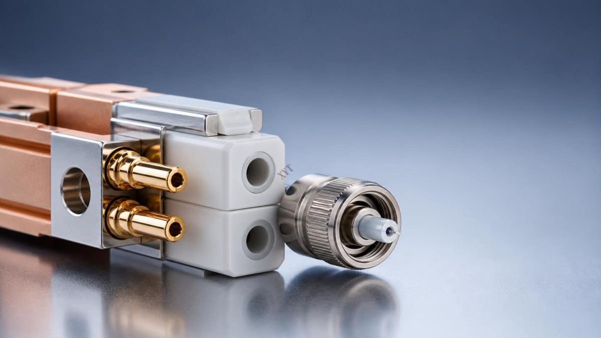
In compact optical connector polishing, this staged approach becomes even more sensitive because the functional area is small and alignment margins can be narrow. One practical example is the use of XYT Lapping Film for VSFF MMC16, MMC24, MMC32 Polishing in polishing flows for high-density optical interconnect formats used in data centers, telecom, and high-speed optical systems. A sequence built around 15 µm, 3 µm, 1 µm, and 0.5 µm abrasive grades can be used to remove larger imperfections, refine the surface after coarse polishing, bring the fiber surface close to defect-free condition, and then achieve an ultra-fine finish. The value of such a sequence is not the number of steps by itself; it is the controlled reduction of surface damage and geometry variation at each stage.
Pressure, Contact Mechanics, and Fixture Compliance
When a finishing process produces inconsistent results, pressure is often recorded as a single setpoint even though the part experiences a distribution rather than a single value. Real contact pressure depends on fixture flatness, pad compressibility, part protrusion, film support, and local wear. In high-tolerance parts, especially those with small functional zones, slight nonuniformity in contact can create measurable geometry drift.
A rigid fixture can improve positional repeatability but may amplify local high spots if the incoming part variation is not tightly controlled. A more compliant system can average those variations, yet too much compliance may round edges or reduce geometry precision. There is no universal correct choice. The right balance depends on whether the process priority is flatness, edge retention, curvature control, or surface defect removal. In electrical contact components, for example, edge preservation may matter because burr suppression cannot come at the cost of altering spring features. In ferrule or optical end-face work, curvature and apex offset control may dominate.
Pressure stability over time is as important as nominal pressure. Pneumatic systems can drift with supply fluctuations, while mechanical loading can change as fixtures wear. If a polishing machine uses multiple stations, station-to-station variation should be separated from abrasive variation during root-cause work. Otherwise, a film lot may be blamed for a flatness problem actually caused by one slightly tilted carrier plate.
The interaction between pressure and abrasive size also deserves attention. A coarse abrasive under excessive pressure can drive deeper fractures or embed particles. A fine abrasive under too little pressure may merely burnish the existing topography, giving low removal and high sensitivity to contamination. Stable finishing recipes therefore control pressure as part of a material removal model, not as an isolated machine setting.
Thermal Effects and Why Light Damage Can Still Matter
Finishing is often perceived as a low-heat operation compared with grinding, but local temperature rise can still affect consistency. On metals, heat can change oxide formation, soften smeared residues, or alter lubricant behavior. On polymers and some composites, it can create softening, drag marks, or edge deformation. On optical assemblies and precision ceramics, thermal expansion mismatches within fixtures may subtly change pressure distribution during the run.
Even modest heating can matter when a process depends on a tight removal window. If lapping oil or polishing liquid viscosity shifts during a long run, abrasive transport and debris evacuation may change with time. Early parts in the batch may see a different cutting regime from later ones. That kind of drift often shows up as a gradual trend rather than a sudden defect spike, which makes it harder to diagnose unless removal rate and end condition are tracked across the full production interval.
Thermal effects are also linked to cleaning. A warmer surface can dry residues unevenly, leaving films that influence contact resistance, adhesion, or inspection results. In high-tolerance electrical parts, those residual films may not be obvious until a coating, soldering, or bonding step behaves erratically. Precision Surface Finishing Solutions therefore include fluid choice, temperature awareness, and post-process cleaning discipline as part of the consistency strategy.
Debris Control Is a Surface Quality Variable
Loose abrasive particles, removed substrate fragments, degraded pad material, and environmental contaminants can all create defects that appear random even though the mechanism is systematic. A single oversized particle trapped in the interface can generate a scratch that forces rework or rejection. Repeated sporadic scratches often point to debris transport problems rather than abrasive grade selection.
Debris control starts with the fluid path and the condition of the contact surface. Dry films, lubricated films, and slurry-assisted processes each have different contamination risks. In dry or semi-dry operations, particles may accumulate at the leading edge of the contact zone. In slurry-based systems, agglomeration and settling can distort effective particle size. If storage conditions allow moisture ingress or particulate contamination into consumables, defects may emerge long after the incoming inspection window has closed.
Handling practices also matter. Touching active film surfaces, stacking parts after finishing without adequate separation, or moving cleaned parts through dusty zones can erase the benefit of a controlled polishing recipe. In optical and fine electrical applications, the final surface may need protection from fibers, packaging debris, and oil residues from gloves or fixtures. Consistency is therefore partly a logistics issue: the surface must stay stable from finishing through inspection, packaging, transport, and installation.
Inspection Should Match the Failure Mode Being Controlled
A common source of false confidence is using the wrong inspection method for the risk that actually matters. Stylus roughness testing may capture average roughness but miss localized defects or directional lay that affects sealing. Visual inspection at low magnification can miss edge chips or subsurface fractures. Conversely, extremely sensitive optical methods may flag harmless cosmetic variation and trigger unnecessary process changes.
For high-tolerance parts, inspection usually works best when layered. Surface texture measurement, optical microscopy, flatness or geometry verification, and application-specific functional tests each answer different questions. If a polished ceramic seat fails unpredictably in assembly, profile measurement alone may not explain the problem; local edge integrity may need to be inspected under magnification. If a conductive terminal shows unstable contact behavior, contamination analysis and surface chemistry may be more revealing than roughness numbers.
Correlation matters more than volume of data. A finishing process should be assessed against the defect modes that truly drive performance variation. For instance, if fiber end-face quality is linked to insertion loss sensitivity and geometry control, then the inspection strategy must focus on scratch state, end-face cleanliness, and geometry rather than relying only on generic surface roughness. If seal life is the issue, waviness and lay direction may deserve more attention than a polished appearance.
Transport and Packaging Can Undo a Controlled Finish
Surface consistency does not end at the polishing machine. High-tolerance parts are vulnerable to recontamination, abrasion, and edge damage during internal transfer and external shipment. Soft metals can mark each other in trays. Fine polished ceramics can chip at unsupported corners. Optical faces can pick up residues from packaging films or shed particles from foam inserts. A part that leaves finishing in good condition may arrive at assembly with a different effective surface state.
Packaging should therefore be selected according to contact sensitivity, not only dimensional protection. Parts with polished functional zones may need individual separation, non-shedding materials, and orientation control. If corrosion-sensitive surfaces are involved, volatile residues, moisture exposure, and temperature cycling in transit should be considered because they can alter oxide behavior and cleaning burden. For long transport routes, vibration can turn minor tray movement into cumulative rubbing damage on fine finishes.
Receiving inspection should also account for packaging-induced changes. When parts arrive with unexplained scratch patterns or particulate films, the finishing process is often questioned first, even though the damage occurred after release. A clear separation between process-generated defects and handling-generated defects helps avoid unnecessary parameter adjustments that do not address the real cause.
Installation Conditions Change the Meaning of Surface Quality
Some surfaces are finished to perform under a very specific assembly or service condition. A contact surface polished for dry mating may behave differently if a thin lubricant film is later applied. A ferrule end-face prepared for one connector geometry may not behave the same way under altered polishing pressure or mating force. A finely finished shaft can lose its intended benefit if installation introduces misalignment or contamination.
That means finishing should be evaluated with the actual installation context in mind. Torque, insertion force, thermal cycles, vibration, humidity exposure, cleaning agents, and mating material all affect whether a given surface state remains stable. In electrical equipment, a surface that is too smooth can sometimes be problematic if it reduces retention of a necessary functional film. In another application, the same smoothness may be beneficial because it limits particle generation or lowers insertion loss. The desired finish is conditional on the joint or interface design.
Installation tooling is part of that context. If assembly fixtures introduce skew or point loading, they may expose geometry variation that did not appear during bench inspection. A finishing process should therefore be validated not only against lab metrology, but also against real assembly behavior where practical.
Optical Interconnect Components Show the Principle Clearly
Among electrical and electronic applications, high-density optical interconnects offer a clear example of why Precision Surface Finishing Solutions affect consistency so strongly. The polished end-face has to satisfy geometric and surface conditions simultaneously. Small deviations in end-face quality can alter alignment, reflection behavior, debris sensitivity, and insertion performance. Because the contact area is limited and the channel density is high, process variation that might be tolerated in a larger interface becomes much more visible.
In polishing formats such as MMC16, MMC24, and MMC32, the abrasive progression has to balance material removal with geometry preservation. Coarser films are used to remove larger imperfections and establish the surface, but staying too long at that stage may deepen defects or shift geometry. Intermediate and fine films then need enough cutting action to erase the prior scratch field rather than simply glossing over it. Ultra-fine finishing reduces residual defects and can support a cleaner interface. Specifications such as SC15B, SC3A, SC1A, SC1B, SC1C, SC1D, and CE0.5B illustrate how multiple abrasive grades may be used within a tightly controlled polishing flow, with each stage contributing a distinct change in surface condition.
Where high-density optical systems are involved, geometry control often matters as much as final appearance. A repeatable process may contribute to better fiber geometry control, lower risk of insertion loss associated with imperfect end-face quality, durable polishing behavior over multiple cycles, and more stable pass rates when the rest of the assembly process is also controlled. Those outcomes depend on the full polishing system, including film condition, tooling, pressure, cleaning, and inspection, rather than on any single consumable in isolation.
Another issue in optical polishing is debris carryover between steps. If coarse particles remain on fixtures or films during transition to a finer stage, random scratch defects can emerge even when the fine film itself is stable. Clean transfer discipline, dedicated cleaning materials, and clearly separated work zones may be necessary when defect thresholds are narrow. The same principle applies outside optics as well. Any high-tolerance finish can be compromised if abrasive carryover is not managed.
Surface Finishing in Conductive and Insulating Components
Electrical equipment spans both conductive and insulating materials, and the finishing logic differs accordingly. In conductive metals such as copper alloys, brass, aluminum, nickel-plated components, and stainless contact hardware, the surface affects mating force, oxide behavior, plating adhesion, and local current distribution. Burr removal and edge conditioning may matter as much as roughness because sharp remnants can cut mating surfaces or generate unstable wear debris.
For plated components, pre-plate finishing has a strong influence on coating uniformity. Deep scratches or smeared areas can translate into thickness variation or weak adhesion zones after plating. Post-plate polishing, if used, must avoid thinning critical regions or contaminating the surface. Very aggressive polishing on soft plated layers can create drag, expose underlying material, or alter contact behavior in ways not obvious from appearance alone.
Insulating ceramics, glass-filled components, and engineered polymers present different concerns. Crack initiation, chipping, fiber breakout, and heat sensitivity may dominate. Ceramics often require control of both flatness and edge integrity because a local flaw can propagate during assembly stress. In polymer-based electrical insulators, overly aggressive finishing may close surface pores or smear material, affecting bonding or coating behavior. The objective is a controlled functional surface, not maximum gloss.
When Flatness and Waviness Matter More Than Roughness
Many high-tolerance parts fail consistency targets because the process focuses on micro-roughness while ignoring form errors such as waviness, taper, or local dish. A very smooth surface can still misbehave if the interface does not distribute load evenly. This is common in sealing faces, heat transfer interfaces, precision guides, and optical carriers. If the component only contacts around the perimeter or at isolated high spots, the assembly may show variable pressure distribution even though the roughness data look acceptable.
Flatness control during finishing depends on machine condition, platen quality, part support, and wear behavior of the consumable. As films wear, their cutting character can change across the working area. If the process does not manage that wear through replacement intervals, indexing, or controlled paths, the same nominal cycle time may yield different geometry on early and late parts. Evaluating form consistency therefore requires looking across tool life, not only at a fresh setup.
Waviness becomes especially important on thin or flexible parts. During finishing, a compliant part may conform temporarily to the support surface and then relax after release, revealing hidden form variation. If inspection occurs before the part stabilizes, measurements can be misleading. Fixturing and metrology need to account for that behavior, particularly on thin metallic laminations, flexible connector components, or slender insulating elements.
Consumable Life Is a Controlled Variable, Not a Footnote
One reason finishing consistency drifts in production is that consumables are treated as static items. In reality, films, pads, slurries, and lubricants evolve during use. The abrasive may dull, the backing may compress, the pad may glaze, and the fluid may accumulate fines. Each change shifts the removal mechanism.
Consumable life should therefore be defined by process behavior, not only by elapsed time or part count. In one operation, the limiting factor may be a falling cut rate. In another, geometry drift appears before cut rate changes noticeably. In another still, sporadic deep scratches rise because the surface begins to trap debris late in life. Tracking the actual failure signature of the consumable gives a more reliable replacement rule than using a generic schedule.
Storage before use matters as well. Films kept under poor temperature or humidity conditions may curl, age, or lose dimensional stability. Pads can harden. Fluids can separate. When a production line sees unexplained variation after a period of low usage or a change in warehouse conditions, consumable storage is worth investigating. Stable results depend on the condition of the consumable at the point of use, not simply on its catalog specification.
Cleaning Between Finishing Stages Is Part of the Removal Model
Between-stage cleaning is often treated as housekeeping, but in high-tolerance finishing it functions as a process step. If residue from a coarser stage remains on the part, fixture, or machine surface, the next stage inherits uncontrolled abrasives. That can lead to deep random scratches, poor geometry, or misleading inspection outcomes. The cleaner the final tolerance window, the more important this becomes.
Effective cleaning depends on the substrate and residue type. Water-based cleaning may be suitable for some materials, but others may require solvent-compatible methods or low-residue surfactants. Soft brushes, filtered air, lint-controlled wipes, or ultrasonic cleaning may be appropriate in some cases, though each introduces its own risks if not matched to the part. Ultrasonic energy can damage delicate edges or assemblies if used indiscriminately. Wipes can leave fibers. Compressed air can redeposit particles if the supply is not clean.
The cleaning sequence also affects drying marks and residual films. On optical and electrical contact surfaces, a trace film that seems minor can alter interface behavior or trigger false visual defects. Cleaning should therefore be qualified against actual surface performance, not assumed to be neutral.
Procurement Specifications Often Miss the Real Process Variables
When finishing consumables are sourced for precision work, oversimplified specifications can introduce variation before production begins. Calling for a generic abrasive type and micron grade may not capture the properties that drive consistency: particle distribution, coating uniformity, backing thickness, compressibility, roll slitting quality, lot traceability, shelf condition, or packaging cleanliness. Two products that share the same nominal grit can behave differently enough to shift the process window.
For high-tolerance parts, incoming qualification should therefore extend beyond label comparison. Trial runs should observe material removal stability, scratch signature, geometry retention, and behavior over the intended consumable life. It is also useful to confirm whether the product arrives in a condition compatible with the process environment. In precision optical or clean finishing operations, packaging debris and storage exposure can affect results just as much as abrasive chemistry.
Another common issue is substitution without revalidation. A seemingly minor change in backing stiffness or lubricant recommendation may alter pressure distribution and surface outcome. Where tolerances are narrow, interchangeable on paper does not always mean interchangeable in process.
Maintenance of Finishing Equipment Is Part of Surface Control
A polishing process cannot remain consistent if the machine drifts mechanically. Worn bearings, uneven platen surfaces, fixture looseness, spindle runout, degraded pressure regulators, and contaminated fluid lines can each create surface variation that resembles consumable instability. Because those issues may develop gradually, they are often misread as random production noise.
Routine maintenance in this context should focus on variables that directly change the contact state between part and abrasive. Platen flatness, rotational accuracy, fixture seating, pressure response, and fluid delivery consistency deserve more attention than cosmetic machine condition. A machine can look acceptable while producing subtle but meaningful form errors. Conversely, a machine with visible wear may still run consistently if the critical contact variables remain under control.
Maintenance intervals should reflect process sensitivity. High-tolerance polishing of optical or precision electrical interfaces generally requires tighter attention than rough deburring or nonfunctional finishing. Verification artifacts, reference parts, or periodic surface signatures can help distinguish machine drift from material drift when problems arise.
Interpreting Rework Signals Correctly
Rework trends often contain the earliest warning that a finishing process is losing consistency. The pattern of rework matters more than the total count alone. A rise in edge defects may point to fixture wear or overpressure. More random scratches can suggest contamination or abrasive carryover. Geometry-related failures clustered at one machine position may indicate local hardware drift. If rework is simply grouped as cosmetic or dimensional, those signals are lost.
There is also a risk in overusing rework as a normal control method. Every additional polishing pass changes removal history, edge condition, and subsurface state. On some materials, a carefully limited rework path is acceptable. On others, repeated finishing can create more instability than it removes. Rework criteria should therefore define when a part can safely return to a previous stage and when the damage mode makes recovery unreliable.
Surface-sensitive parts may also require distinct handling after rework because they have already passed through one full contamination and cleaning cycle. If that is ignored, rework can become a separate source of variation rather than a corrective action.
Matching Finishing Strategy to Part Geometry
Not all high-tolerance parts should be finished with the same contact geometry. Flat parts, cylindrical parts, stepped features, miniature bores, ferrules, slots, and patterned surfaces each respond differently to abrasive contact. A process that is stable on an open flat face may fail on a recessed feature because debris cannot escape. A film-backed system may suit one profile while a pad or slurry process suits another. The finishing method needs to respect where the abrasive can cut, where pressure concentrates, and where the part is vulnerable to edge rounding.
Small features create special challenges because the fixture often becomes part of the contact geometry. If the support area is too broad, the feature may not see enough local pressure to cut consistently. If support is too narrow, edges may overcut. On miniature electrical and optical components, these interactions can dominate the outcome more than raw abrasive size does.
Complex geometry also raises orientation effects. If a part always enters the abrasive in the same direction, lay and edge wear may develop asymmetrically. Controlled rotation, oscillation, or indexing can reduce that pattern, but only if the machine path and fixture repeat it accurately.
Surface Chemistry Can Shift Functional Consistency
The mechanical finish is only part of the final surface state. Oxides, adsorbed films, cleaning residues, and embedded abrasive fragments can change how a surface behaves electrically, optically, or chemically. In conductive applications, a visually clean surface may still show inconsistent contact behavior if oxide thickness varies with storage and post-finish handling. In bonding applications, a low-energy residue can reduce wetting. In optics, a thin contamination film can interfere with inspection and performance.
Because of this, a stable finishing solution often includes attention to chemistry after the last abrasive step. Parts may need controlled drying, low-residue cleaning agents, or limited exposure to reactive environments before packaging. For some materials, rapid passivation is beneficial. For others, it may be detrimental to the next process step. The correct handling sequence depends on the intended function of the surface and the time interval before assembly.
Surface chemistry also affects shelf life after finishing. A part that remains stable for a short assembly window may not stay equivalent after longer storage. If finished components are stocked before use, that storage period should be considered during validation.
Process Windows Should Be Built Around Defect Escape, Not Ideal Parts
During development, it is tempting to optimize a finishing recipe around the best-looking parts produced under favorable conditions. That approach often creates a narrow process window that struggles in routine production. A more reliable method is to understand how defects escape when variables drift slightly: a worn film, a small pressure offset, a minor change in incoming surface condition, or a longer hold time between cleaning and inspection.
By studying the boundary conditions, it becomes easier to define robust operating limits. For example, a process may tolerate variation in cycle time but be highly sensitive to abrasive carryover. Another may be stable across film age but vulnerable to fixture seating errors. A third may depend strongly on the incoming machining signature, making upstream process control essential. Precision Surface Finishing Solutions improve consistency most effectively when they are treated as part of a larger chain of variation control rather than as a rescue step for unstable upstream manufacturing.
This is particularly important where incoming parts arrive with mixed surface conditions from multiple machining tools or suppliers. The finishing stage can absorb some of that variation, but only within a defined removal budget. If incoming scratches exceed what the process is designed to remove, final consistency will fluctuate no matter how carefully the polishing step is run.
Common Misreadings During Root-Cause Analysis
Several recurring mistakes complicate troubleshooting in high-tolerance finishing. One is assuming that a roughness improvement always indicates process improvement. If the surface becomes smoother because it is smearing rather than cutting cleanly, performance may actually become less stable. Another is treating sporadic scratches as proof of a bad abrasive lot without checking cleaning, handling, and machine contamination paths. A third is blaming the final polishing stage for geometry errors introduced two steps earlier.
There is also a tendency to change multiple variables at once when results drift. Switching film grade, pressure, cycle time, and cleaning method together may recover yield temporarily, but it hides the true mechanism. In precision work, it is usually more effective to isolate the contact mechanics first, then the consumable behavior, then the handling path. The surface itself often reveals which order to follow if the defect morphology is examined carefully.
Another misreading occurs when inspection is performed on too small a sample of the surface. A central spot may appear acceptable while the outer ring or edge zone carries the real defect pattern. In components where the functional load sits near the edge or across a narrow band, whole-surface observation matters more than a convenient measurement location.
Integrating Material Removal with Downstream Operations
Consistency in high-tolerance parts is strengthened when the finishing process is linked explicitly to what happens next. If the next step is bonding, the finish should support wetting and bondline stability. If plating follows, the pre-finish should control scratch depth and cleanliness. If assembly requires press-fit or low-force insertion, edge condition and friction behavior become central. A finishing process chosen in isolation may optimize the wrong attribute.
Downstream coating and sealing steps are especially sensitive. A surface polished too finely can reduce mechanical anchoring for some coatings, while a surface left too coarse may create voids or thickness variability. In thermal interfaces, waviness may dominate performance more than micro-roughness. In optical alignment features, geometry stability across batches may outweigh peak smoothness once a certain defect threshold is achieved.
That is why effective Precision Surface Finishing Solutions are usually defined by acceptable downstream behavior and repeatability, not by a standalone surface number. The more tightly the finish is connected to the real assembly path, the less likely it is to drift into a cosmetic specification that does not protect function.
Where Fine Films Fit in a Controlled Finishing System
Film-based lapping and polishing media are often selected when uniform abrasive presentation, repeatable backing structure, and controlled progression between stages are needed. They can be particularly useful on small, high-value, or geometry-sensitive parts where random slurry behavior is undesirable. Their strength lies in predictability, provided film choice matches the material and the machine path supports even contact.
In high-density fiber applications and other miniature precision interfaces, a staged film system may offer good control over both defect removal and geometry maintenance. Coarser films such as 15 µm grades can prepare the surface and remove larger imperfections. Intermediate 3 µm films refine the resulting topography. Finer 1 µm grades reduce residual defect depth, and ultra-fine 0.5 µm stages can support a cleaner final finish. The exact transition points, however, depend on the substrate, fixture, inspection criteria, and allowable removal.
Where a process requires specific grade options for adjustment, specifications like SC15B, SC3A, SC1A, SC1B, SC1C, SC1D, and CE0.5B may provide flexibility to tune the sequence. That tuning should still be based on observed surface response and geometry control rather than on assuming that a finer grade automatically solves a defect. Fine films are most effective when each stage has a defined corrective task.
For polishing flows involving MMC16, MMC24, or MMC32 configurations in compact optical interconnect work, a controlled film progression can help maintain enhanced fiber geometry control and a stable ultra-fine finish when handling, cleanliness, and fixture alignment are also tightly managed. In that context, the finishing medium is one part of a broader consistency system rather than a standalone fix.
Operational Signals That a Finishing Process Is Healthy
A healthy finishing process tends to show stable removal behavior, predictable transition between abrasive stages, low sensitivity to ordinary operator variation, and defect signatures that remain recognizable when something does go wrong. Randomness is usually a warning sign. If failures shift from geometry to scratches to contamination without any clear pattern, the process may be operating without enough control over one or more hidden variables.
Another good sign is when minor incoming variation produces proportionate outgoing variation rather than amplified scatter. That indicates the finishing sequence is absorbing normal upstream differences within its designed removal capacity. If small incoming changes cause large swings in the final result, the process window is probably too narrow for routine production.
Stable finishing also shows coherence between measurement systems. Geometry, roughness, microscopy, and functional inspection should tell a compatible story. When one method says the surface is improving while the functional outcome says otherwise, the process is likely being evaluated through the wrong lens or the wrong measurement location.
Precision Surface Finishing Solutions improve consistency when they are built around actual interface behavior, disciplined abrasive progression, controlled pressure distribution, clean handling, and inspection that can see the defects that matter. In high-tolerance parts used across electrical equipment and related precision assemblies, that approach reduces hidden surface variation and makes the finished part behave more like its drawing intends.
Awesome! Share to:
Related Posts
- ◉ China Tightens Abrasive Exports: Carbon Footprint Declarations Required for US and EU Shipments from August 15
- ◉ EU REACH Rules for Nanoparticle Silica Take Effect August 15
- ◉ When Is Cerium Oxide Film Used for Connector End-Face Finish?
- ◉ Diamond vs. Silicon Carbide Lapping Film for Connectors
- ◉ How Should MTP Polishing Parameters Be Tuned?
Get in Touch
*We respect your confidentiality and all information are protected.